
Credits: A.J. Wodack
Somewhere on the High Plains in Colorado
May, 2002
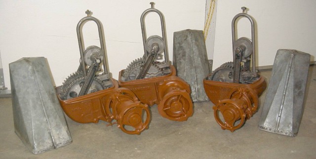
One of the most popular windmills out there, the Aermotor 702 windmill is simple, quick and easy to re-build. The parts to re-build this mill are readily available, and the replacement parts with it's exchange capabilities means, no pouring Babbitt. That is, not unless you really want to……
Because of this, the Aermotor 702 windmill is an excellent mill in order to get your "feet wet" for the novice, and learn the basics, and mechanics of windmills. Once you do one, your hooked into windmillin', and can't wait to start a new windmill project, weather it's another Aermotor or another make. The principles learned here can be applied to these other makes as well, with some slight modifications of procedures.
An excellent book, by Mr. T. Lindsay Baker, "The 702 Model Windmill", covers most every aspect of the 702. (It's not currently in print, just check the internet - editor). I would suggest getting one, there is a lot of useful information here!
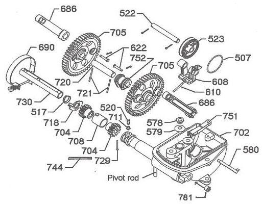
I would like to share my re-building techniques. Hopefully they would be useful for the novice, and experienced windmiller alike. There are some "tricks of the trade" that isn't readily known. I won't be delving into ripping the mill apart. The only comment I'll make here is…… Some mills come apart easy, and others you'll have to ‘work' at. Just figure on the latter, if your luck is anything like mine…… You might also want to keep in back of your mind, is to remove the oil collector #520 from the hub when your tearing into the windmill.
Once the mill is completely disassembled, a good cleaning is in order!! I prefer torching the cast iron parts with a weed burner, burning the old grease and oil out of it. At times the oil will actually catch fire and eventually burning itself out. The ash and dirt are then easily scrapped and wire brushed off. From here I sand blast the mill to have an nice clean shinny carcass to work with. Prior to the 'burning' I melt out the Babbitt, and save it for re-pouring for this project or others in the future. If you don't feel comfortable by burning the mill, feel free to use other options of cleaning, like the hot tank (acid bath dipping).
 'Crispy Critters' These mills were BBQ with the propane weed burner.
 This is what you can expect after sand blasting that burnt up windmill.
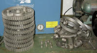 Parts were sand-blasted, as well
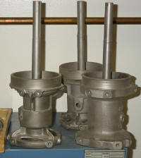 And the hubs, too...
With the cleaning done examine your parts, carefully. Pay ATTENTION to DETAILS!! Look at those pinions, boss gears, hub, and mainframe, your checking for wear and cracks in the casting. More likely than not you'll be replacing those pinion gears, pins, shaft, and of course all the Babbitt. Maybe a new set of boss gears, or other parts is in order. You should have a good idea on what your going to need after this examination.
As far as I know, there isn't a 'spec' sheet on the tolerance or 'play' that is allowed in building the mill. So a lot of common sense is needed here. If there seems to be too much play in a part, there probably is…..
However, most of the guess work is taken out by purchasing a re-build kit. There are 3 re-build kits available from different manufacturers.
The #770 bearing kit that includes parts #520, 708, 730, 752, 729, and two 721.
The #707 kit includes everything in the #770 kit plus two #686 and a 744.
Then there is the #777 overhaul kit which includes the #707 kit plus a #507, 517, 522, 610, 718, 720, two 622, and two 704.
I'm not sure why these kits, especially the #777 kit doesn't include the #510 vane pin. I have yet to see a mill that didn't need one!! So I include this part in my order.
With kit in hand, it's time to put things back together. First clean up those new parts in solvent and wipe them dry. Dry fit those new parts onto your mill parts, paying particular attention to the pinion gears' placement onto your hub shaft. Make sure they slide effortlessly on the shaft. If there is any score marks or 'mushrooming' at the end of the shaft, now would be the time to take care of the problem. Not when your trying to get things together!! Everything should just slip together smoothly without any need of a hammer to get things to fit.
The next thing I check is the pitman guide hoop, #508 for excessive looseness or 'play'. Moving it from side to side will indicate this. Most generally all that needs to be done here is re-set the #508R pins by 'peening' them. Worse case scenario, is you'll need to replace the #508R pins. (HINT: You may want to remove the hoop and knurl the ends if looseness persists.)
Moving on to the boss gear assembly. The bearing, #752 needs a slight modification. There is no oil grove or channel in the bearing, so oil dispersing is hindered at this point, I feel. As most of the pressure and subsequent wear occurs at the bottom of the #752 bearing. Additional oil flow would help. What I do is add an oil grove by doubling up hack saw blades and cutting a grove, carefully between the oil valley on the top end of the bearing. Just going deep enough, about the depth of the saw blade teeth (this is a judgment call). I then use a razor sharp blade to clean up around the oil valley and the grove I just made. Oiling up the shaft and bearing, I place these together.
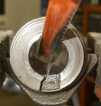 Using a doubled hack saw blade, an oil grove is cut into the #752 boss gear bearing in-between the oil galleries.
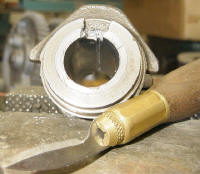 Using a razor sharp carving knife, this is the end result of the cleaned up bearing.
Through out it's original life the boss gears, #705 were riding, basically on one side of the gear teeth. If you reverse these gears (from left to right) you would have a new gear tooth face riding on the pinion gears #704. In essence, it's like having a new set of boss gears to last you another 40, 50, or more years. (HINT: If you turn your hub 'clockwise' and watch the way the pinions are hitting the bosses, that will be the gear tooth side in real life.) I mount the boss gears on the new shaft aligning up the pin holes. Because the boss gears are stationary and not free floating the two boss gears need to be perfectly aligned with each other or else gear 'clunk', and or binding will occur. (Hint: This can also occur if the pinions #704 are not properly aligned with the hub shaft keyway with the #744 key.) Here I use the pitman arm long stroke boss on the gear as my reference point, with tri-square in hand I align the gear teeth on both gears. The #721 pins are then place in the boss gears and bent over. (HINT: Bending one side of the pin in an 90 degree angle in your vise first, will help keep the pin in place as your playing with your combinations.) If the gear tooth alignment has moved after adding the pins, different combinations of the #720 shaft placement can be tried, for instance, rotating the shaft 180 degrees, moving from right side to left. A total of 4 combinations can be tried, alignment will work on one of these combinations. Once that is found, bend the other end of the pin in the opposite direction so it looks like a 'Z' configuration, locking things in place. (HINT: You might want to knurl each end of the #720 shaft after finding the correct combination to tighten the fit between the shaft and gears. But be fore warned that you may have to use a hydraulic press to press the gear back onto the #720 shaft.)
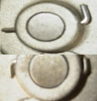 The top picture showing the 90 degree bend made in the vice, and bottom picture showing the 'Z' bend.
Moving on to the hub shaft assembly now... I haven't had too much luck at salvaging the pinion gears from an original mill, (maybe, I'm just too picky here) though I have come across some decent looking pinions from time to time. Generally, I just install new ones. If you happen to get a nice set of used pinions, and want to use them, these too can be rotated from left to right to gain a new gear tooth face if so desired.
Now mount your new bearing #708, making sure the tang of the bearing fits into it's slot on the mainframe. Oiling up the bearing, and the pinions, place the pinions into the bearing. (HINT: You may want to mark the pinion keyway location on the front pinion at this time with a marker. Might save yourself a headache with the alignment, when it comes time to drive the #744 key in.) Now slide in your #730 bearing into the snout of the windmill, this should slide in flush on the front of the snout. (HINT: If your bearing is hard to slide in, use and adequate length of 'all thread' running it through the #781 plug hole, and the snout of the mill. With nuts and washers of appropriate size suck the bearing into the snout. Care must be taken so you don't score the bearing with the threaded rod.) The spout washer #718 and spring #517 are installed next, the spring going in front of the washer, the large diameter portion of the spring going against the spout washer, and the smaller diameter portion of the spring riding against the #730 bearing. Remember when I said Pay attention to detail?? Check to make sure the tit portion of the spout washer is well past the bearing, and the spring is 'springing'. You may need to trim off some slag of bearing material on the #730 bearing for the spout washer to work properly. When everything looks good, oil up the hub shaft and the #730 bearing, sliding the hub shaft home through the pinions. Install the #744 key on the hub shaft, and pinions to lock the pinions in place……. You were able to align the front pinion keyway, weren't you?? Good!! (HINT: A little squirt of WD-40 on the #744 key helps it slide in a little easier.) Now install pin #729, and bend the locking pin in the rear hole of the hub shaft. There are two type of pins that are normally supplied, a straight pin that needs to be bent in the 'Z' configuration, and the 'headed' pin, that is bent in only one direction. (HINT 1: I find if you grind about 1/3 of the head on one side of the 'headed' pin (down equal to the shaft of the pin), the ground head part slides nicely along the side the pinion, and it doesn't bulge out when you drive the #729 pin home.) (HINT 2: You may want to place a slight taper at one end of your #729 pin with your grinder, that way the pin will self align, and won't bottom out on a lip or edge, as your driving 'er home.)
 Using a tri-square, I'm aligning the gear teeth on the #705 boss gears.
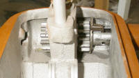 Installed pinion gears, bearings, and spout washer, just prior to the hub and shaft being installed.
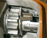 Notice the #708 bearing tang mounted in the mainframe notch (left) and the spout washer tit in the #730 bearing (right).
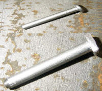 The hub shaft #729 pin, top showing unaltered pin, and bottom showing my modifications to the head and tip.
No tricks are needed in mounting the #522 pin through your yoke #608 and guide wheel #523. Just oil 'er up and put together. Select which stroke option you want, long or short, and mount your oiled #686 pitman arms. Never split the stroke!! (Mounting your pitman arms on the long stroke large gear boss and short stroke (bottom hole) pitman arm hole onto the #522 pin, or the short stroke large gear boss and long stroke (top hole) pitman arm hole.) Your oil ring #507 won't operate properly and the upper end will be starved of proper lubrication. Prematurely, wearing out your mill.
Putting it all together you should have a nice tight, free wheeling windmill ready to work for you. One last check to make sure you have everything put together correctly, and check there is no play between your boss gear bearing saddle #752 and bearing bar #751. The bearing bar tang may have been worn, though this is rare, but an easy fix is at hand if it is. Using a penny or dime (of course the date on the coin should correspond to when you put your mill together... 😉 as a shim between the bearing bar tang and mainframe then re-torque the bolt.
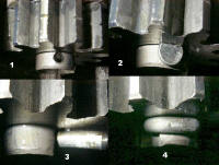 Pin installation in the hub shaft, notice in picture #4 where the pin is wrapped around the shaft.
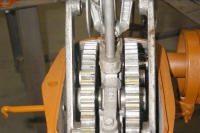 Now is the time to double check your work to make sure everything is correct.
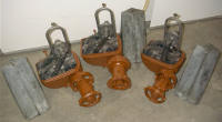 All re-built with new parts. These mills should have a nice long life!
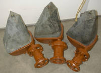 Buttoned up and ready for the field, only waiting for their adornment of sails and vane.
The very last thing to get installed, is the oil collector #520. That doesn't get installed until the sails are mounted. You'll need the sails as a fulcrum to properly 'set' or 'seat' the oil collector. I just find it easier to do it this way. Remove the pipe plug from your hub, turn your hub hole to 'high noon', as if it were the hand on a clock. Using a wide blade slot head screwdriver, screw the oil collector into the snout of the mill. Grabbing the wheel arms of the windmill, turn the hub clockwise about an inch or two, then counter clockwise about the same distance. Progressively going back and forth until a complete revolution or so is made, you'll feel the oil collector seating as your doing this. Re-install the pipe plug in your hub and your ready to go.